

Before cloud communication became the norm, businesses relied on analog PBX systems — complex yet reliable setups that managed internal and external calls through wired connections. Understanding the analog PBX system diagram helps you see how these systems worked, what their limitations were, and why so many companies are now switching to modern cloud PBX solutions.
1. Introduction to Analog PBX System Diagram
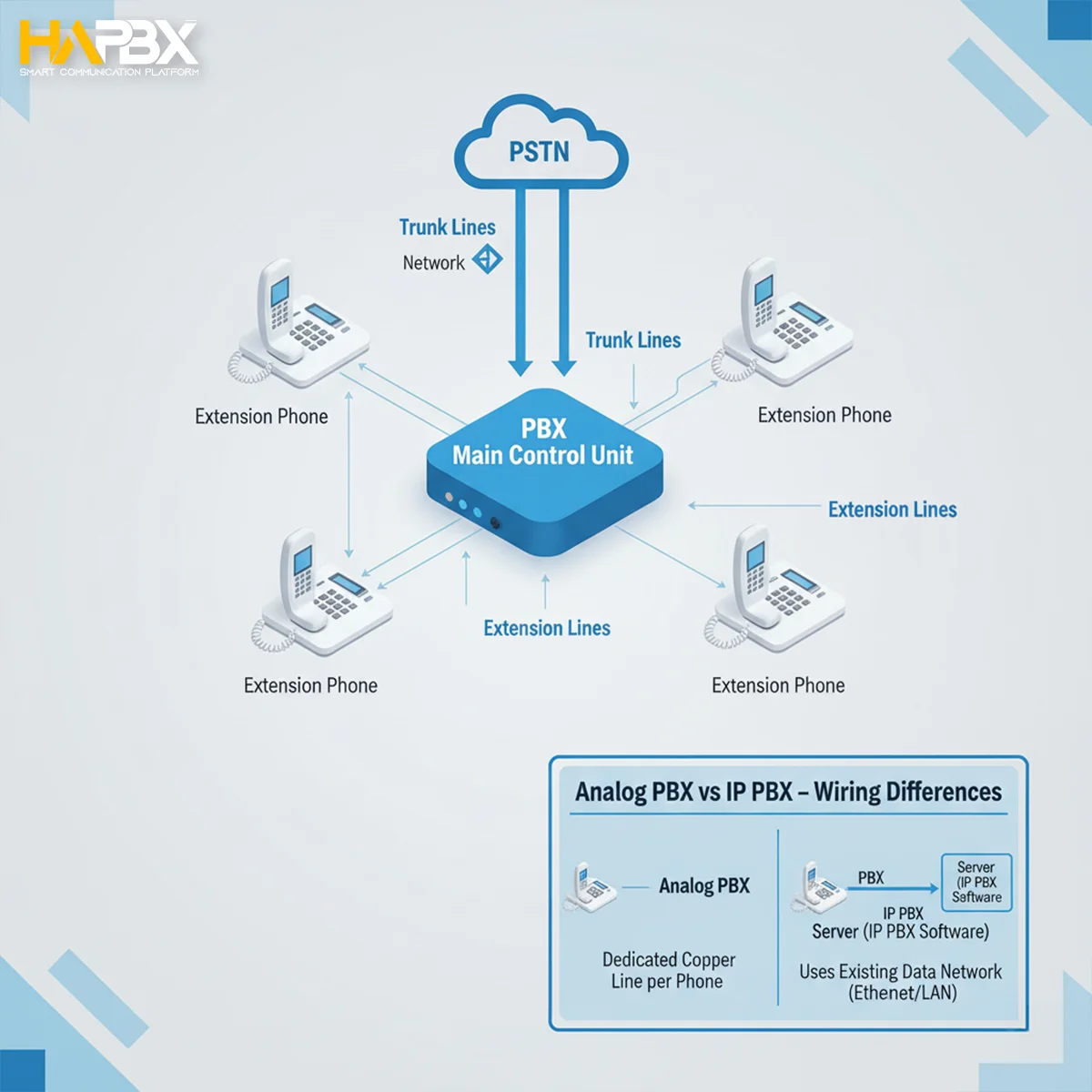
An analog PBX system diagram is the blueprint behind traditional business phone systems. It visually maps how voice signals travel from external trunk lines through the PBX (Private Branch Exchange) to internal extensions.
Before cloud telephony existed, analog PBX systems powered nearly every office — routing internal calls, connecting departments, and linking businesses to public networks. Even today, thousands of companies still rely on these legacy setups for their simplicity and resilience.
Understanding PBX wiring diagrams is crucial for maintaining consiste\nt communication quality. They help IT teams troubleshoot line issues, design structured cable layouts, and prevent costly wiring mistakes.
Key components of a typical analog PBX system include:
- Analog lines (Trunks): External phone lines connecting the PBX to the PSTN.
- Extensions: Internal phones or desk sets connected to the PBX.
- Punch Down Blocks: Termination points for structured wiring.
- PBX Control Unit: The core device managing call routing and signaling.
2. Understanding the Analog PBX System Diagram
Analog PBX systems distribute voice signals through copper lines. The PBX control unit receives incoming calls from the PSTN (Public Switched Telephone Network) and routes them to internal extensions. Similarly, when a user dials an external number, the PBX selects an available trunk line for the outgoing call.
A typical analog pbx system diagram shows:
- Trunk lines feeding into the PBX main unit.
- Extension ports branching out to multiple wall jacks.
- Optional punch down blocks for structured connection.
Comparison: Analog PBX vs. IP PBX
| Feature | Analog PBX | IP PBX |
| Connection Type | Copper wiring (RJ-11) | Ethernet (RJ-45) |
| Signal Type | Analog voice signals | Digital packets |
| Infrastructure | Physical wiring and punch blocks | LAN/WAN-based with minimal cabling |
| Scalability | Limited by ports | Highly scalable via software |
| Maintenance | Manual troubleshooting | Remote monitoring and updates |
| Integration | Standalone | Easily integrates with CRMs and UCaaS |
“The analog PBX system remains a foundation of business telephony — and understanding its wiring diagram is the first step toward reliable communication.”
Solutions like HAPBX preserve this reliability while modernizing it — offering a hybrid bridge between analog hardware and cloud-powered voice routing.

3. Punch Down Wiring in Analog PBX Systems
“Punch down wiring” is the process of connecting copper wires into small metal slots within a block — creating a secure and permanent connection. These blocks (commonly 66, 110, or Krone blocks) serve as structured termination points for all phone lines.
Types of punch down blocks:
- 66 Block: Standard in North America, used for voice circuits.
- 110 Block: Common in modern telecom rooms, supports both voice and data.
- Krone Block: Popular in Europe and modular installations.
Proper pbx wiring through punch down blocks ensures:
- Consistent signal quality.
- Organized cable management.
- Easier testing and maintenance.
4. Step-by-Step Wiring Guide for an Analog PBX System
Setting up an analog PBX system requires careful planning, proper tools, and precise wiring. Below is a detailed guide that helps you wire your system safely and efficiently while keeping your setup organized and easy to maintain.
4.1 Planning Your Wiring Layout
Before running any cables, begin by mapping out your PBX wiring diagram. This ensures all extensions, trunk lines, and connection points are clearly identified.
Locate your Network Interface Device (NID):
The NID is the handoff point between your building’s internal network and the Public Switched Telephone Network (PSTN).
It’s usually mounted near the main entry point of the phone service.
Identify your Distribution Frames:
- MDF (Main Distribution Frame): The central hub where all external and internal lines meet.
- IDF (Intermediate Distribution Frame): Secondary points used for larger buildings or multiple floors.
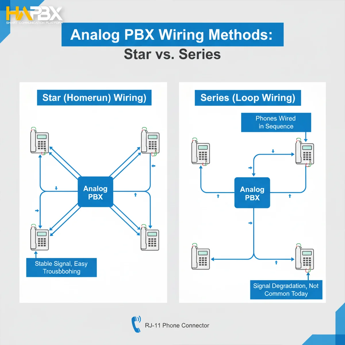
Choose your wiring topology:
- Star (Homerun):
Each phone has its own dedicated cable running directly to the PBX.
✅ Best for larger offices where individual extensions need to be easily managed and replaced.
- Series (Loop):
Each phone connects in sequence along the same line.
✅ Simpler installation but less flexibility for future upgrades or troubleshooting.
💡 Tip: Always label every cable run during planning. This saves hours of confusion during maintenance or expansion.
4.2 Wiring Connections
Once your wiring layout is planned, begin the actual PBX wiring process following these steps carefully:
Connect trunk lines from PSTN to PBX input terminals:
These incoming lines provide external connectivity. Secure them on the PBX’s “LINE IN” or “TRUNK” ports.
Run extension cables from the PBX to user locations:
From the PBX’s “EXT” or “STATION” terminals, wire each line to wall jacks or directly to desk phones.
Keep cables organized in bundles, separated from power wiring to avoid interference.
Maintain polarity:
In analog systems, correct polarity ensures stable line voltage and call clarity.
- Tip = Green wire
- Ring = Red wire
Connect tip-to-tip and ring-to-ring between all devices.
Secure connections on punch-down blocks:
Use a 110 or 66 punch-down block to terminate each pair neatly.
Label each row with extension numbers for easy reference.
⚠️ Caution: Avoid connecting PBX phones directly to standard analog terminals — the voltage difference can damage both devices.
4.3 Tools and Materials Needed
To wire your analog PBX system diagram effectively, prepare the following:
| Tool / Material | Purpose |
| Punch Down Tool | Terminates wires on the block securely |
| 22/24 AWG Twisted Pair Cables | Standard cable for analog voice signals |
| RJ-11 or RJ-14 Connectors | Connect phone lines and extensions |
| Cable Tester | Checks continuity and detects wiring faults |
| Label Maker / Marker | For marking extensions and trunk lines |
Color Codes for Analog PBX Wiring
| Wire Color | Line Assignment |
| Red / Green | Line 1 (Primary) |
| Yellow / Black | Line 2 (Secondary) |
💡 Pro Tip: For large-scale installations, consider using 25-pair cables with standard color codes (Blue, Orange, Green, Brown, Slate groups) to simplify wiring and expansion.
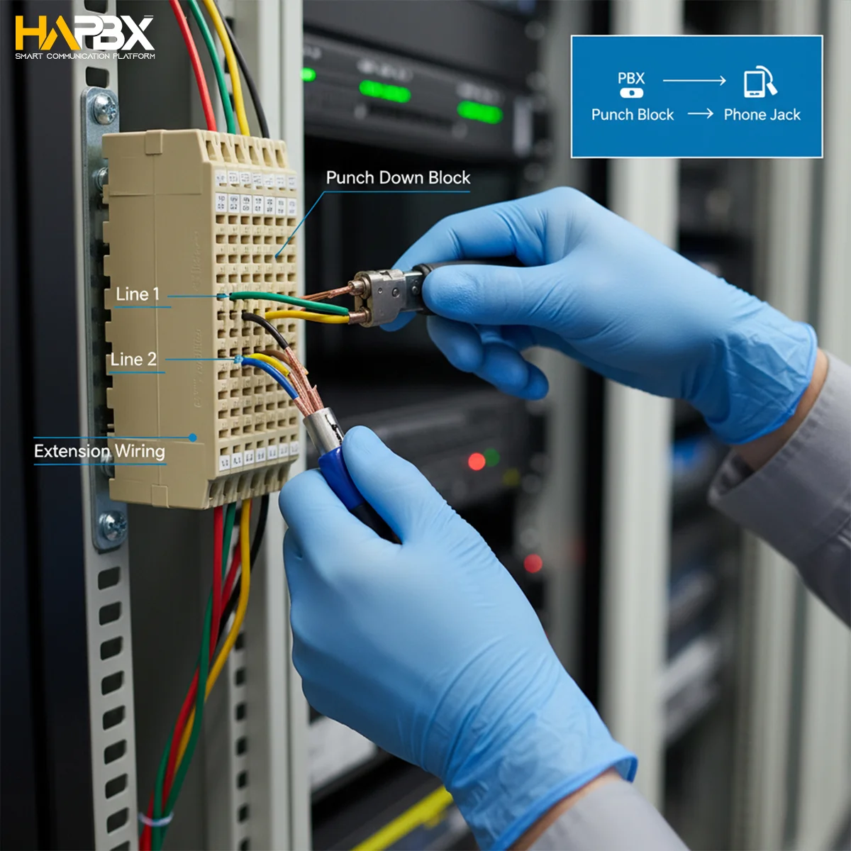
“Proper punch down wiring is not just about neatness — it defines the reliability and clarity of every call your PBX handles.”
5. Analog PBX System Diagram Explained (Visual Reference)
A complete pbx wiring diagram typically includes:
- Central PBX Unit – The core switching device.
- Trunk Lines from PSTN – External lines carrying incoming/outgoing calls.
- Extension Lines – Internal desk phones or fax machines.
- Punch Down Blocks – Physical junctions between trunks and extensions.
- Optional IP Gateway – For hybrid or VoIP integration.
Each element communicates through the PBX, ensuring that calls are routed correctly without signal interference.
6. Configuration After Wiring the PBX System
Once wiring is complete, configuration begins. You’ll define:
- Extensions: Assign numbers to each desk.
- Ring Groups: Group extensions for departments.
- Dial Plans: Set rules for internal and external call routing.
- Call Management: Control blocking, forwarding, or busy signals.
For example, in systems like Asterisk or Ozeki Phone System, admins can manage these directly through a GUI interface.
Modern systems such as HAPBX take this a step further — enabling cloud-based configuration without any on-site server.
7. Common Analog PBX Wiring Issues and Troubleshooting
Some frequent wiring problems include:
- No Dial Tone or Static Noise: Often caused by loose punch down connections.
- Crossed Wires: Mixing tip/ring pairs leads to noise or call dropouts.
- Broken Pairs: Damaged copper lines interrupt signal continuity.
To troubleshoot:
- Test continuity with a line tester.
- Verify punch down seating.
- Check line polarity.
Regular testing prevents downtime and ensures consistent voice quality.
8. Integration with Modern Communication Systems
Today’s businesses often combine analog systems with digital enhancements. You can integrate an analog PBX using:
- VoIP Gateways: Convert analog voice into digital SIP signals.
- SIP Trunks: Replace physical lines with virtual connections.
This hybrid analog-IP setup allows gradual migration — keeping legacy phones while enjoying VoIP flexibility.
“With solutions like HAPBX, businesses can upgrade from analog PBX to cloud PBX without replacing their entire infrastructure.”
HAPBX bridges analog and digital seamlessly — managing routing, voicemail, and analytics in one cloud-managed interface.
9. Q&A
Q: Can I use my old analog phones with a new PBX system?
A: Yes, through ATA (Analog Telephone Adapters) or VoIP gateways.
Q: How many extensions can an analog PBX support?
A: It depends on port capacity — typically 8 to 128 per unit.
Q: Is PBX wiring still relevant in the cloud era?
A: Absolutely — structured wiring ensures physical reliability, even when the logic moves to the cloud.
10. Conclusion
An analog pbx system diagram remains one of the most valuable tools for visualizing business telephony. It helps engineers plan efficient wiring layouts, minimize interference, and maintain call reliability.
While analog PBX systems are robust, integrating them with modern platforms like HAPBX brings scalability, automation, and cloud intelligence — ensuring your communication system is ready for the future.